Projects
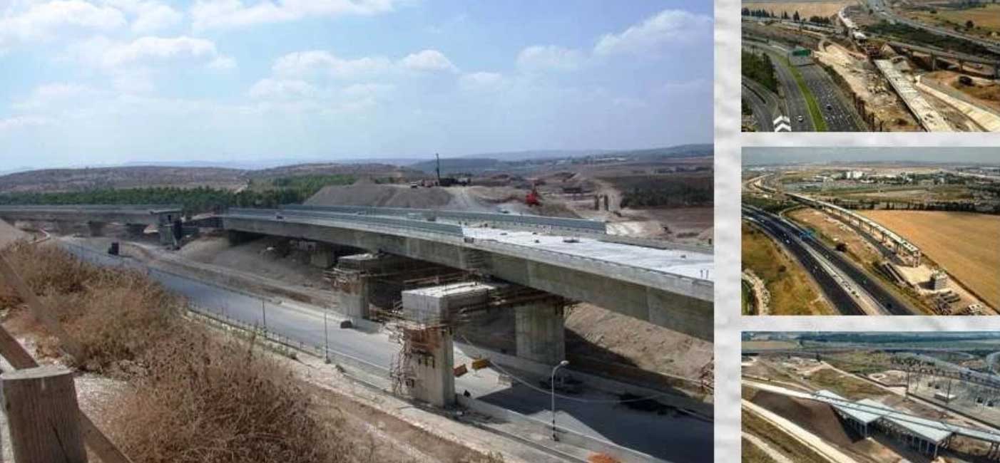
Natbag-Modein Railway
Railroad in the length of approx. 20 km
Natbag – Modein Railroad is an integral part of line A1 up to the split in the Aneba interchange area (the first railroad interchange in Israel). Simultaneously the road transfers passenger traffic to Modein.
The main designer of the railroad is D.A.L development and engineering Inc. Construction designer is Pakatz Engineering (1997) Inc. and the project manager is Dana Engineering Inc. Ltd.
The railway pass passes through road crossing areas and different nuisances and is packed with structures like bridges, tunnels and retaining walls. In a railroad in the length of approx. 20km, there were over 4.0km of double track railway bridges, over 2km of Cut&Cover tunnels, approx. 1.0km of deep tunneling and about 12.5km of retaining walls designed and built.
The railroad bridges were designed and built with spans matching the crossing conditions in a number of different technologies, including the most advanced of them. Amongs the bridges that were built two were built using the balanced cantilever method, four using the incremental launching method and the rest were made of precast beams or cast in situ.
Engineer structures of the railroad were made for a number of tenders by leading contractors in the field of infrastructure building in Israel – Danya Sibus, Ter Arma, Linom, Minrav, Solel Bone, Ramet, and Shafir.
Natbag – Modein line could be defined as the first modern railway done in Israel in the aspect of engineer structures. Just for illustration, we’ll mention that with the building of the railway the length of bridging per single railway has become five times bigger compared to the existing length prior to it. As for today, among the structures of this line there is the longest bridge in the net of railways in Israel – about 1.1km (is assembled of 4 bridges), the longest incremental launching method bridge in Israel – full length about 700m when the incramental launching method was used on both sides (bridge 15 – approx.. 430m and bridge 14 – approx. 230m), biggest span between two railway bridges – 78.0m (bridge 16) and the largest span between bridges executed using the incremental launching method in Israel – about 66m (bridge 1.4).
The construction of the railway structures was done over a very short period of time – the time from the beginning of the design to the end of the construction is under four years, and that includes a process of receiving statutory certificates to the execution documents.
One of the special traits of the railway structures is a combination of erection methods, static schema and different structural elements in the bridges of the line. A need for that was dictated by the gabarit limitations in the crossings of the existing roads and railways on the one hand, and the aspiration to minimize the costs as much as possible on the other.
A noticeable example to these cases is bridge 1 – a prohibition against putting pylons in the channel of the Ayalon canal required the execution of larger spans in bridge 1.1 – up to 72m (built in the balance cantilever method). Later, a gabarit limitation in the entrance/exit roads from Natbag combined with a relatively large span (up to 42m) required the making of a structure with small height (2.1m) from precast elements in order to lower traffic disruptions. This section was made of joined beams, continued by a section in free conditions that was made using a pair of precast beams with 33m spans , which is a very wise solution financially. The crossing section of road number 1 was made in the incremental launching method with spans up to 66m to enable free traffic during the construction. The operating contractor of the bridging works is Solel-Bone Ltd.
The combination of different structures with changing heights and different structural elements required special architectural solutions that give the bridge it’s uniqueness by the similar architectural design of the basic elements (pier shapes, cornis, rails, etc…) including the design of the fillers that bear the changes in the coarseness of the elements.
The choice of solutions for the railway bridges was chosen based on the analysis of mutuality between the structure of the bridge to the establishment technology and was established on three main factors – structural solution, building technology, and technical means the executors possess.
A final decision about the structural solution was (usually) based on a comparison of financial efficiency that includes the money saved, the speed of execution and the routine maintenance expenses, when in certain cases the additional elements that effect the choice were architecture and environmental reservation requirements. This comparison brought on the decision to use solutions that match the equipment and the experiment of the executors, or to bring in new technologies.
An example to the influence of architectural requirements on the structural solution is bridge number 11 that crosses road number 6 in the area of Daniel interchange. The existing road bridge, which was built as cast slap that leans on a system of individual pylons, dictated the architecture of the railroad bridge and the planning of the future roads dictated its length.
On top of that, the aspiration to minimize the costs and the limitations on execution methods brought to an integrated technological solution, in which the center part of the bridge (that passes over an active road with heavy traffic) was designed and built in the incremental launching method and bridging sections above free ground were cast in situ using a casting yard that was built for the incremental launching of the middle section.
As mentioned, the bridge is over 550m in its length and is made of three blocks – central block in the length of 200m using the incremental launching method and two cast in situ bridges in a total length of approx. 350m. The maximal span of the bridge 42.2m and its height is 2.2m. The bridge was made by Linom Ltd. Beside minimizing the costs, combining different erection methods also allowed to shorten the construction schedules by working in parallel with three shells.
Now would be a good time to mention the ability of the contractors in Israel to build bridges in advanced methods, quickly learning new erection methods during the execution, and their ability to effectively draw conclusions and acquire knowledge and experience.
Amongst the contractors that acquired experience in methods unused by them prior to the project: Solel Bone – Balanced cantilever method, Ter Arma – Balanced cantilever method with special bottom form work, Danya Sibus – Incremental launching method, Linom – Incremental launching method.
During the project, the first railway interchange in Israel was designed and built – railway split Natbag – Modein and A1. In the Aneba interchange area, after the crossing of the road number 1 in tunnel 12 in the length of approx. 300m railways split by a system of distributors and a line to Modein passes over railway A1. The length of the structure is 225m and the width moves between 12.5m to 18.5m. The interchange structures were built by Danya Sibus Ltd.
In the continuation of the line bridge 14 was built. It passes over the future course of road 431 to the west, above a connection ramp431 to road 1, and above a future Rishon Le Tsion – Modein railway. The bridge, in the length of approx. 230m with 45m spans, was built using the incremental launching method by Danya Sibus Ltd. A number of central piers of the bridge were planned and built as frame elements from prestressed concrete because of the sharp crossing angle of the line above roads and railways. This bridge was built after road 15 was completed and the connection of the two bridges built using the incremental launching method was done using a common pier that is designed in a way that allows to comfortably disassemble the steel nose.
In the Modein area the railway passes through a narrow strip between the lanes of road 341 that didn’t allow slope execution, which caused a need in putting up a system of retaining and sheet pile walls made in different methods – reinforced soil, structural walls from prestressed concrete, sheet pile walls with and without ground anchors.
We’ll mention another type of structures made during the project – Cut&Cover tunnels – in the crossing of road 1 and in the area of Modein – as a statutory requirement to preserve the acoustic protection in the city.
Among the tunnels structure number 13 stands out with a span of over 30m and filling thickness up to 20m. This tunnel is in the length of approx. 200m and was designed for 4 railways (two housing railways in addition to the main railways) and thus allowing to save the making of another tunnel.v
צרו
קשר
הרוקמים 26, בניין B
חולון, ישראל
טלפון: 03-7916916
פקס: 03-7916917
ד.אלקטרוני: orly@pakatz.co.il